Part 1
Engine Replacement
Special Tools
EN 46114 Lifting Brackets
For equivalent regional tools, refer to Special Tools Special Tools.
Removal Procedure
Note:
The front wheels of the vehicle must be maintained in the straight ahead position and the steering column must be in the LOCK position before disconnecting the steering column or intermediate shaft. Failure to follow these procedures will cause incorrect alignment of some components during installation and result in damage to the SIR coil assembly.
1. Relieve the fuel pressure. Refer to Fuel Pressure Relief (High Pressure) Fuel Pressure Relief (High Pressure)Fuel Pressure Relief (Low Pressure) Fuel Pressure Relief (Low Pressure).
2. Remove the ignition key and lock the steering.
Warning:
Refer to Battery Disconnect Warning Battery Disconnect Warning.
3. Disconnect the battery ground cable. Refer to Battery Negative Cable Disconnection and Connection (Primary) Battery Negative Cable Disconnection and Connection (Primary)Battery Negative Cable Disconnection and Connection (Auxiliary) Battery Negative Cable Disconnection and Connection (Auxiliary).
4. Remove the air inlet grille. Refer to Air Inlet Grille Panel Replacement (Lower Panel) Air Inlet Grille Panel Replacement (Lower Panel)Air Inlet Grille Panel Replacement (Upper Panel) Air Inlet Grille Panel Replacement (Upper Panel).
5. Recover the air conditioning (A/C) refrigerant. Refer to Refrigerant Recovery and Recharging Refrigerant Recovery and Recharging.
6. Remove the air cleaner outlet duct. Refer to Air Cleaner Outlet Duct Replacement Air Cleaner Outlet Duct Replacement.
7. Drain the cooling system. Refer to Cooling System Draining and Filling Cooling System Draining and Filling.
8. Remove the radiator outlet hose. Refer to Radiator Outlet Hose Replacement (LFX) Radiator Outlet Hose ReplacementRadiator Outlet Hose Replacement (L77) Radiator Outlet Hose Replacement.
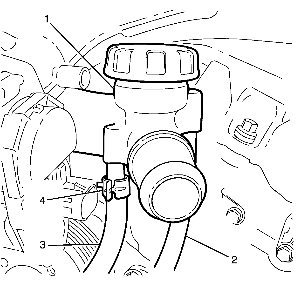
9. Compress the coolant bleed hose retaining clamp (4) at the outlet housing (1) end and slide 50 mm (2 in) along the coolant bleed hose (3).
10. Remove the coolant bleed hose (3) from the outlet housing (1).
Note:
Twist and pull the coolant recovery hose (2) to remove from the outlet housing (1).
11. Disconnect the coolant recovery hose (2) from the outlet housing (1).
Note:
Plugging or capping pipes and hoses prevents leaks or contamination.
12. Plug or cap the cooling system hoses and coolant outlets.
Warning:
Refer to Safety Glasses Warning Safety Glasses Warning
Note:
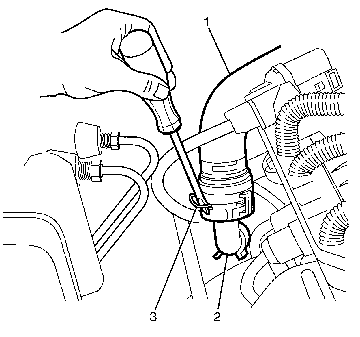
The inlet and outlet heater hoses (1) are retained to the heater pipes (2) by quick connect fittings. Disconnect the heater hoses (1) quick connect fittings by releasing the retaining clips (3) with a suitable tool.
13. Disconnect the heater hoses (1) from the heater pipe (2).
Note:
Apply the brakes several times until the brake pedal becomes firm to deplete the vacuum reserve of the brake booster.
14. Deplete the brake booster vacuum reserve.
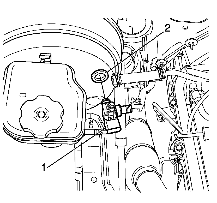
15. Disconnect the engine wiring harness from the brake booster vacuum pressure sensor/check valve (1).
16. Remove the brake booster vacuum pressure sensor/check valve (1) from the vacuum brake booster.
17. Disconnect the engine control module connectors. Refer to Engine Control Module Replacement Service and Repair.
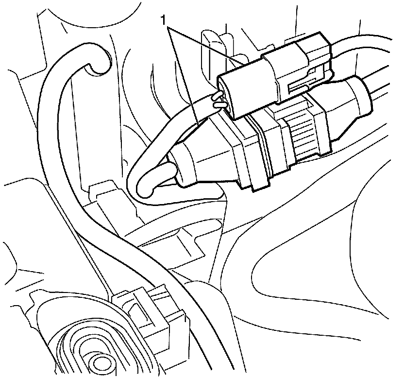
18. Disconnect the engine wiring harness connectors (1) from the main engine wiring harness.
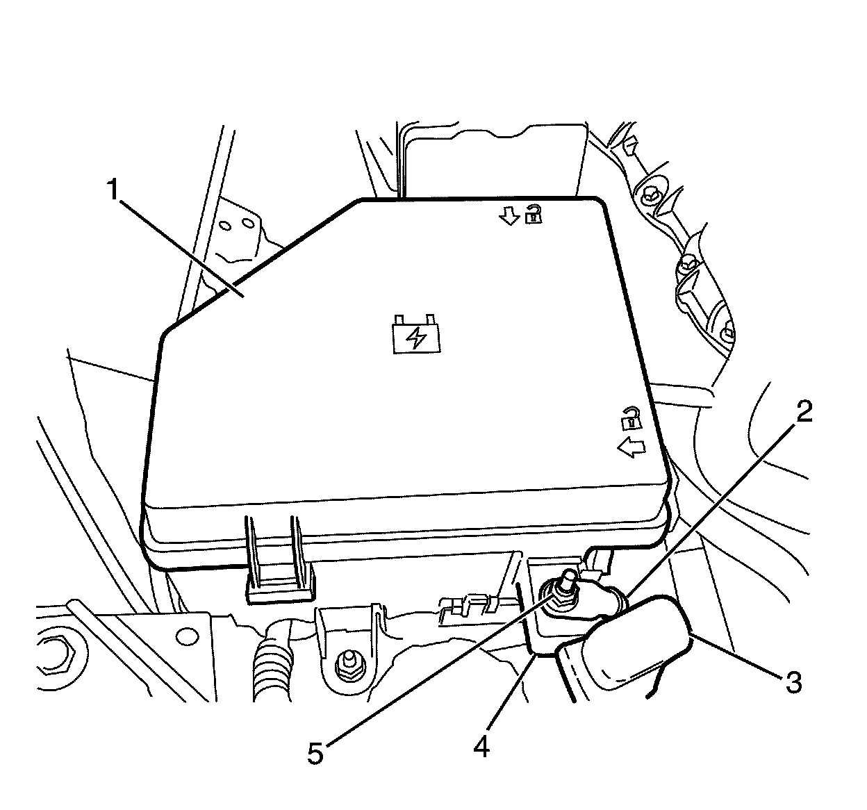
19. Remove the under hood body electrical centre cover (1).
20. Remove the positive cable to under hood plate retaining bolt (5).
21. Disconnect the positive cable (2) from the upper under hood plate (4).
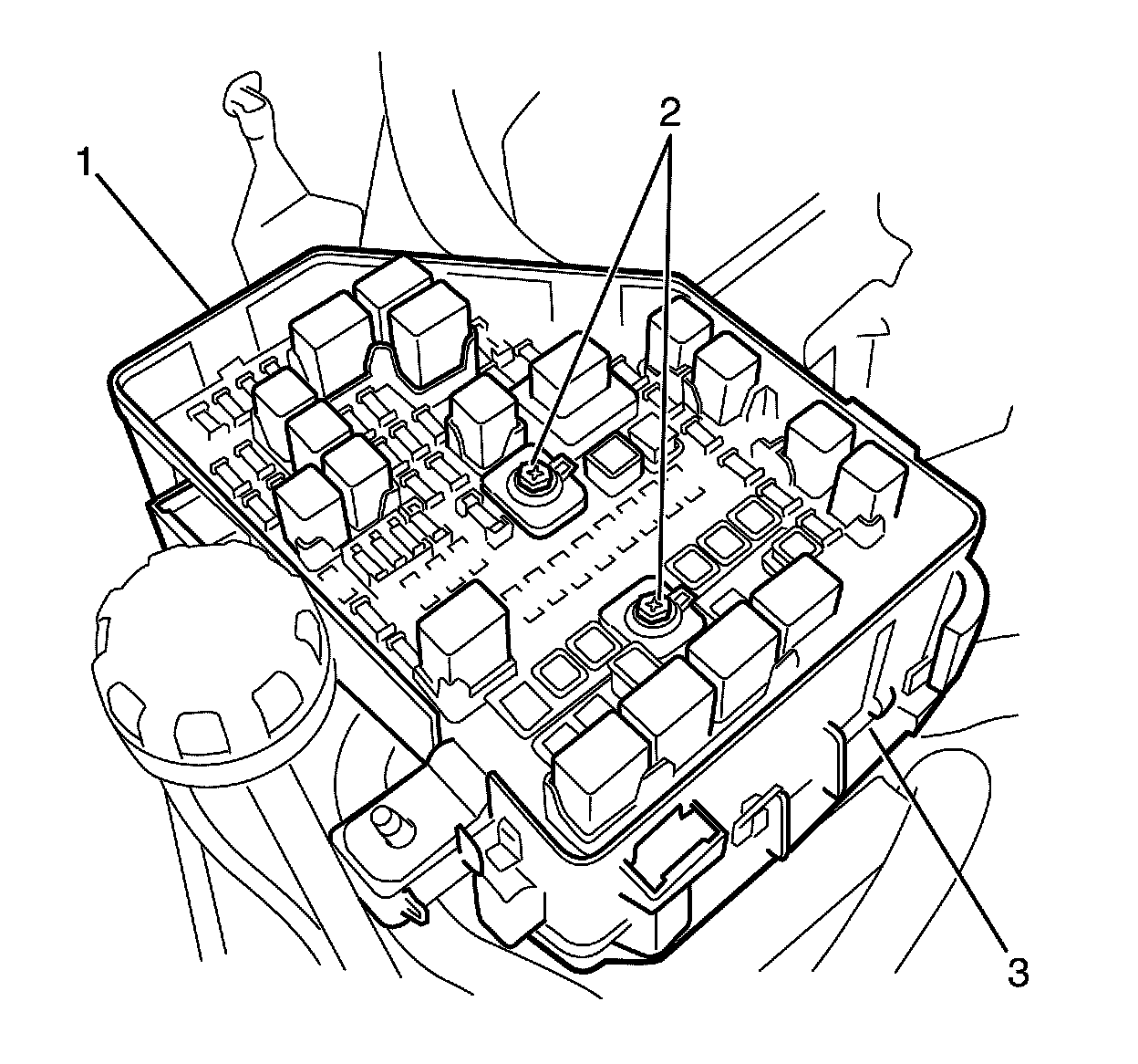
22. Loosen the under hood upper plate to lower plate retaining bolts (2).
23. Raise the upper under hood plate (1) from the lower under hood plate (3).
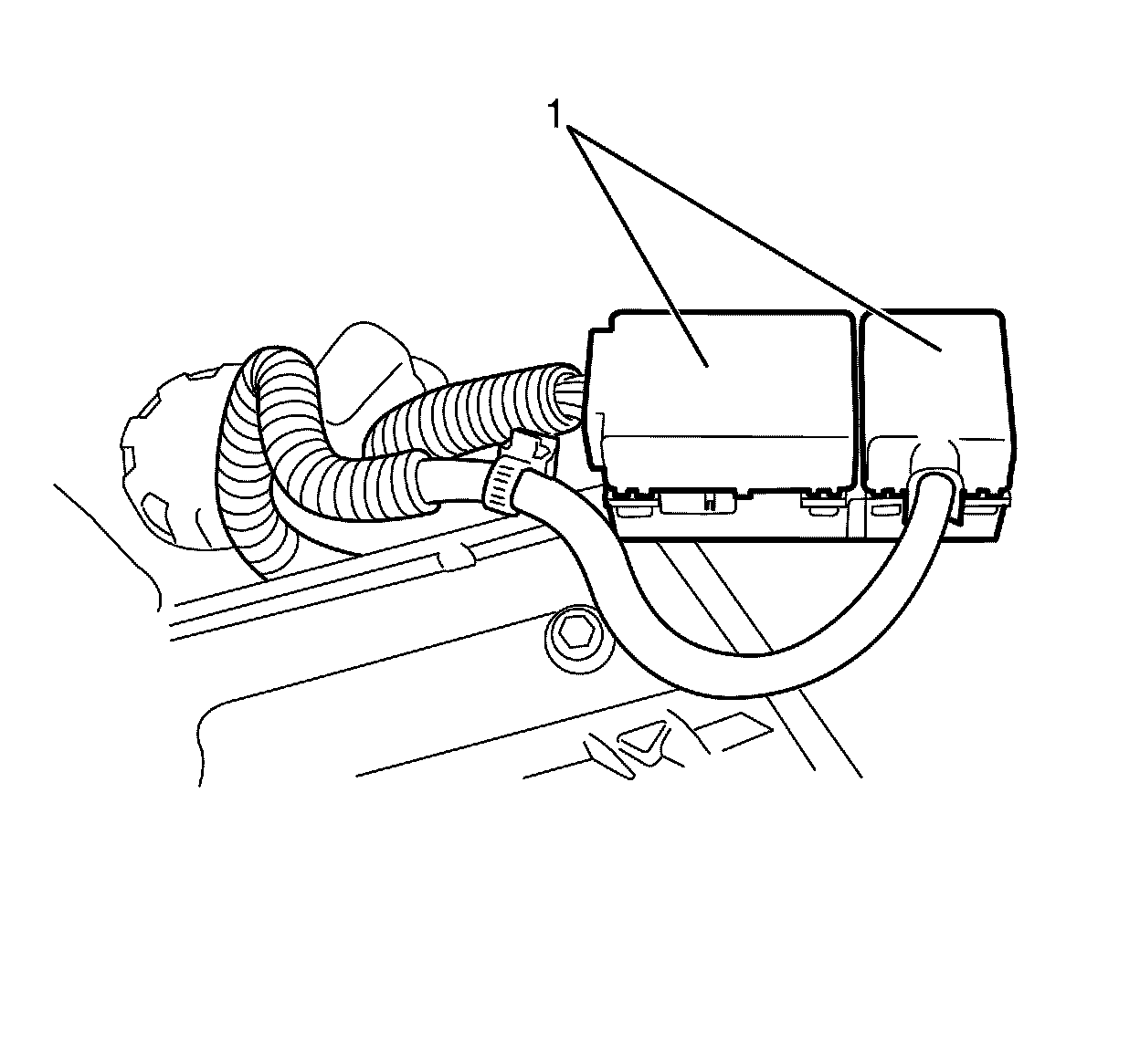
24. Detach the protector (1) from the base of the under hood connector.
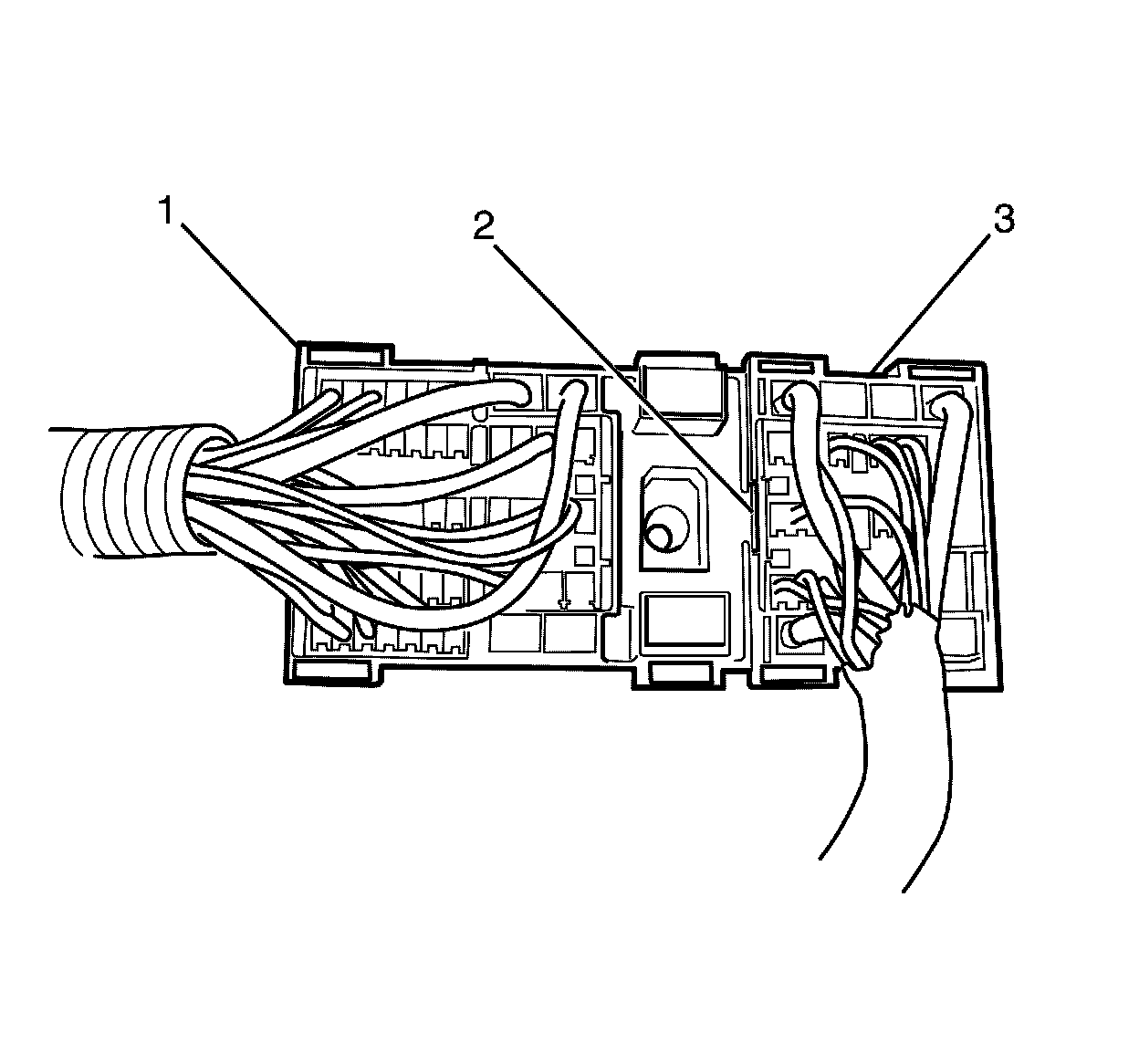
Note:
Use a suitable tool to depress the connector locking tang (2), then pull the body harness connector (1) upward and the engine connector (3) downward to separate the body harness connector (1) from the engine connector (3).
25. Separate the body harness connector (1) from the engine connector (3).
26. Reposition and secure the engine wiring harness and connector (3) on the engine.
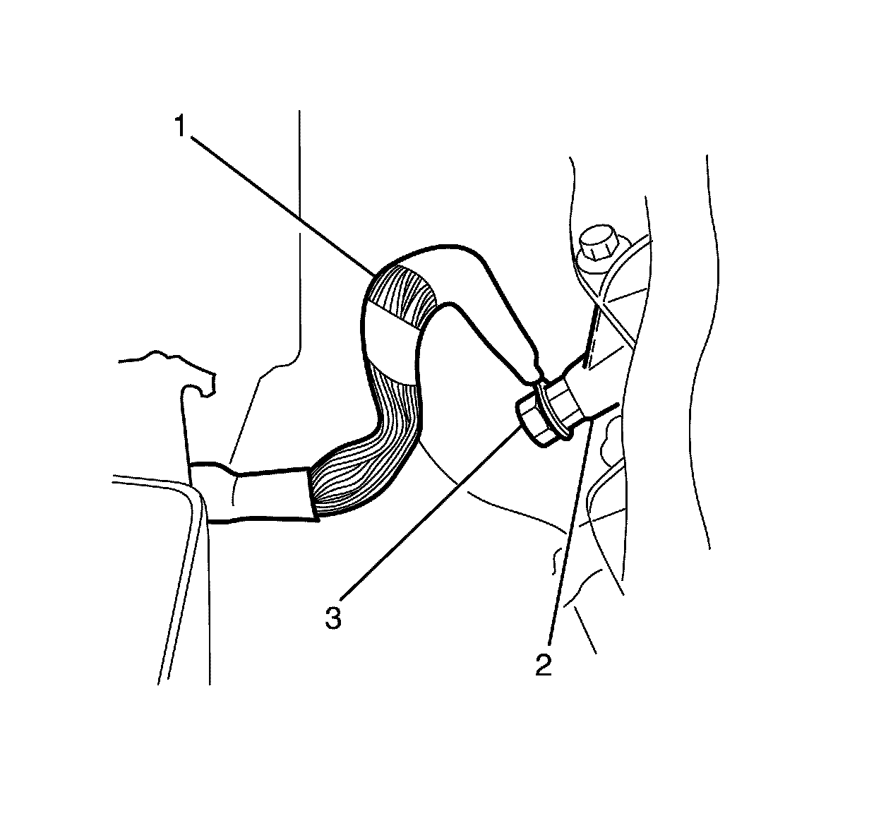
27. Remove the body ground cable to cylinder head ground stud retaining nut (3).
28. Detach the body ground cable (1) from the cylinder head ground stud (2).
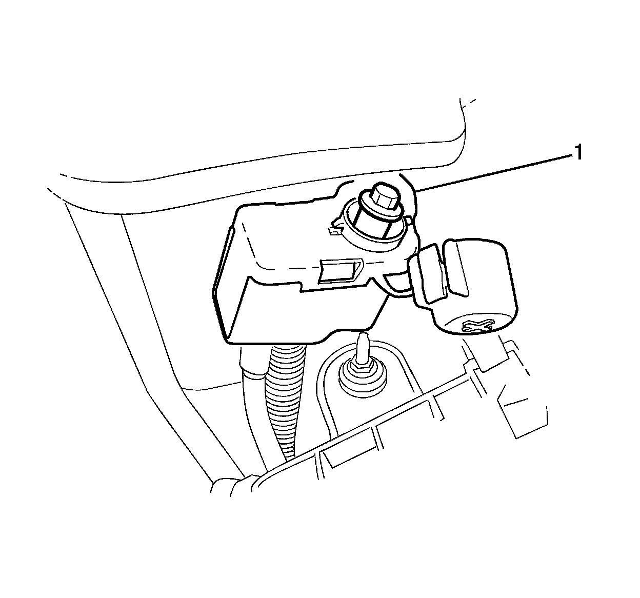
29. Remove the remote battery positive post cover (1).
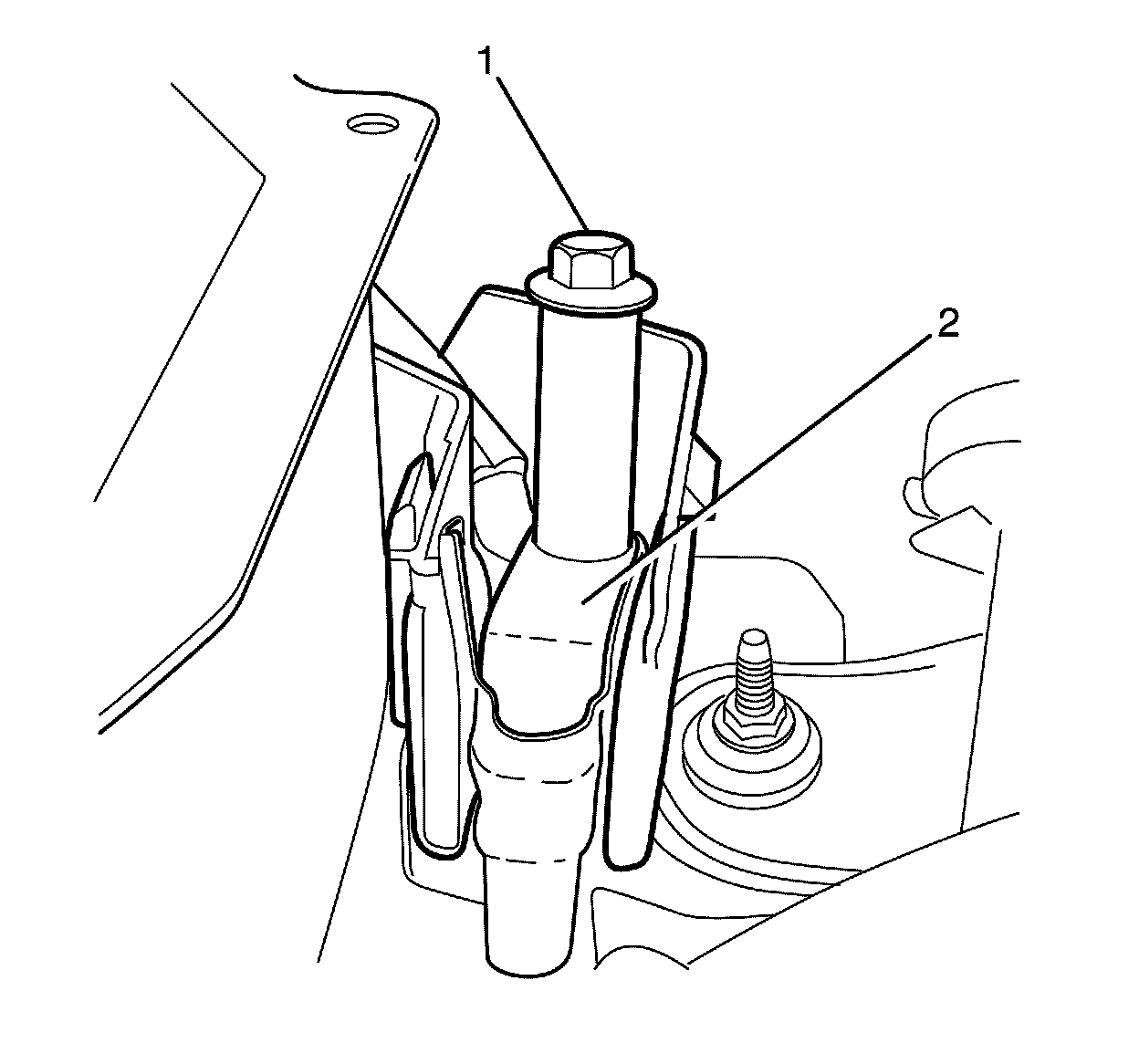
30. Remove the remote battery positive post to wiring harness retaining nut (1).
31. Remove the wiring harness (2).
Danger:
To avoid any vehicle damage, serious personal injury or death when major components are removed from the vehicle and the vehicle is supported by a hoist, support the vehicle with jack stands at the opposite end from which the components are being removed and strap the vehicle to the hoist.
Warning:
Refer to Safety Glasses Warning Safety Glasses Warning.
32. Raise and support the vehicle. Refer to Lifting and Jacking the Vehicle Service and Repair.
33. Remove the front air deflector.
34. Remove the engine splash shield.
35. Disconnect the radiator inlet hose. Refer to Radiator Inlet Hose Replacement (LFX) Radiator Inlet Hose Replacement.
Note:
Plugging or capping pipes and hoses prevents leaks or contamination.
36. Plug or cap the radiator water inlet and the radiator outlet hose.
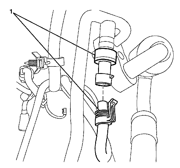
37. Disconnect the A/C pressure transducer electrical connector (1).
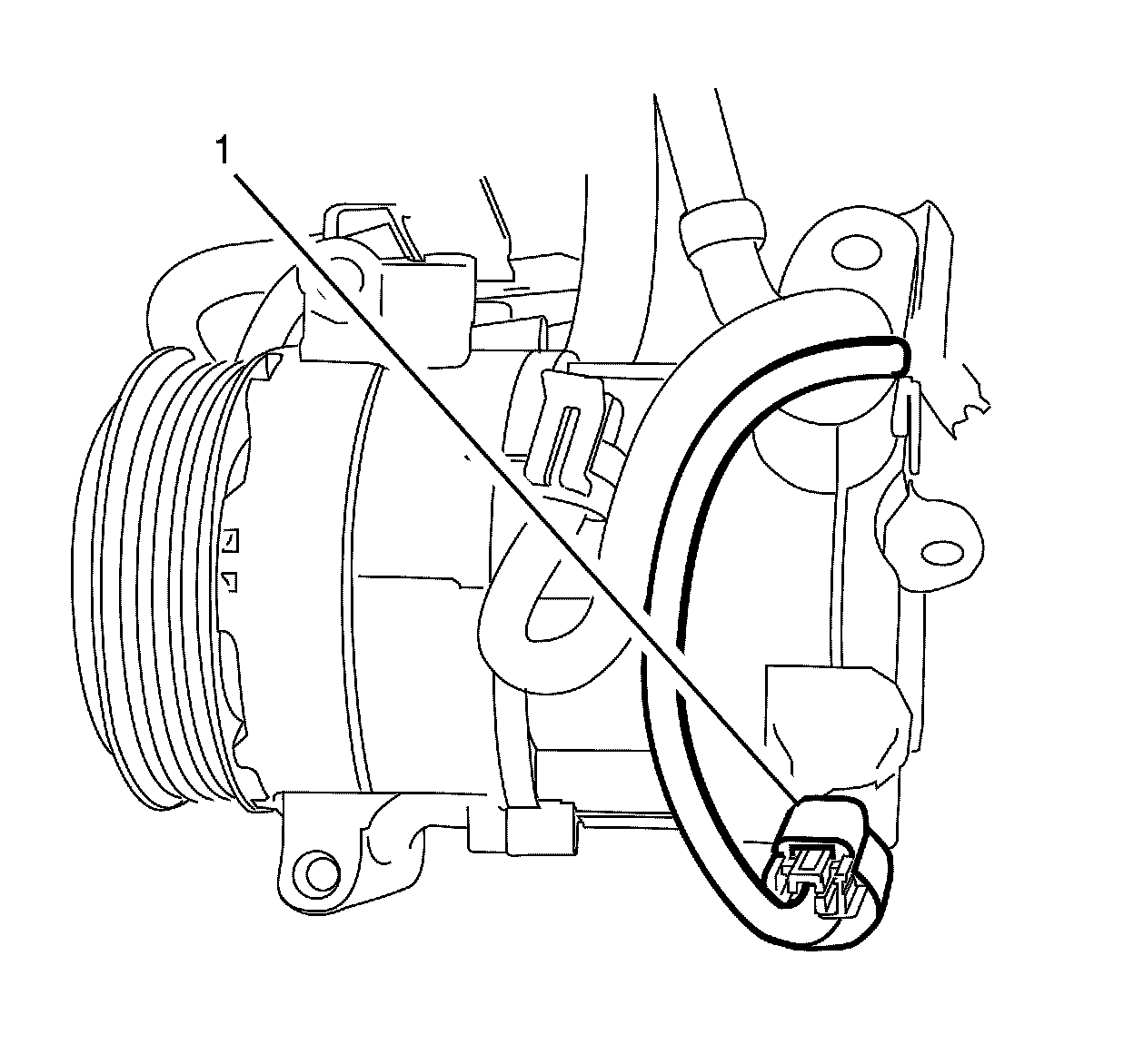
38. Disconnect the A/C compressor electrical connector (1).
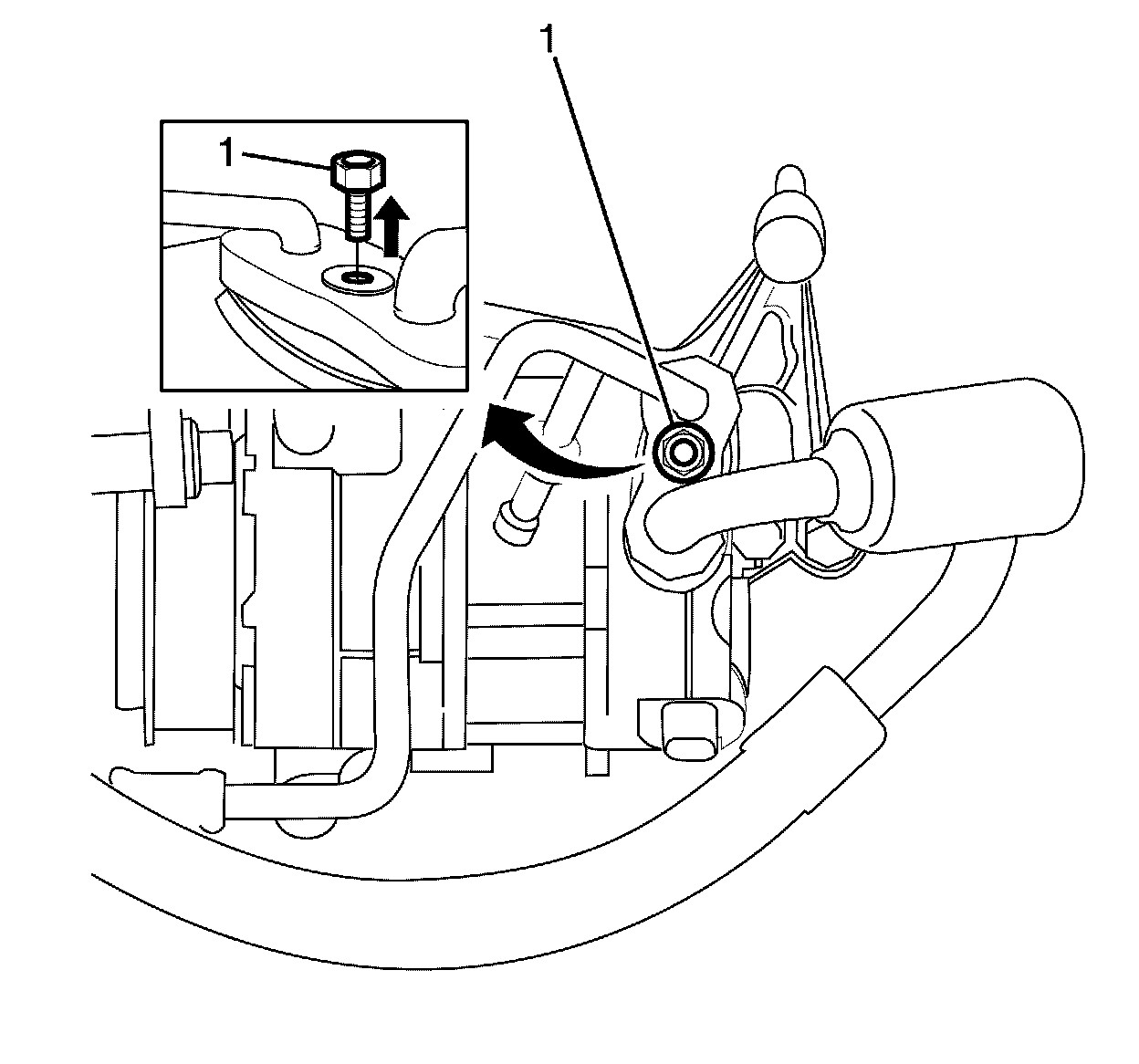
39. Remove the suction/discharge line pad to A/C compressor retaining nut (1).
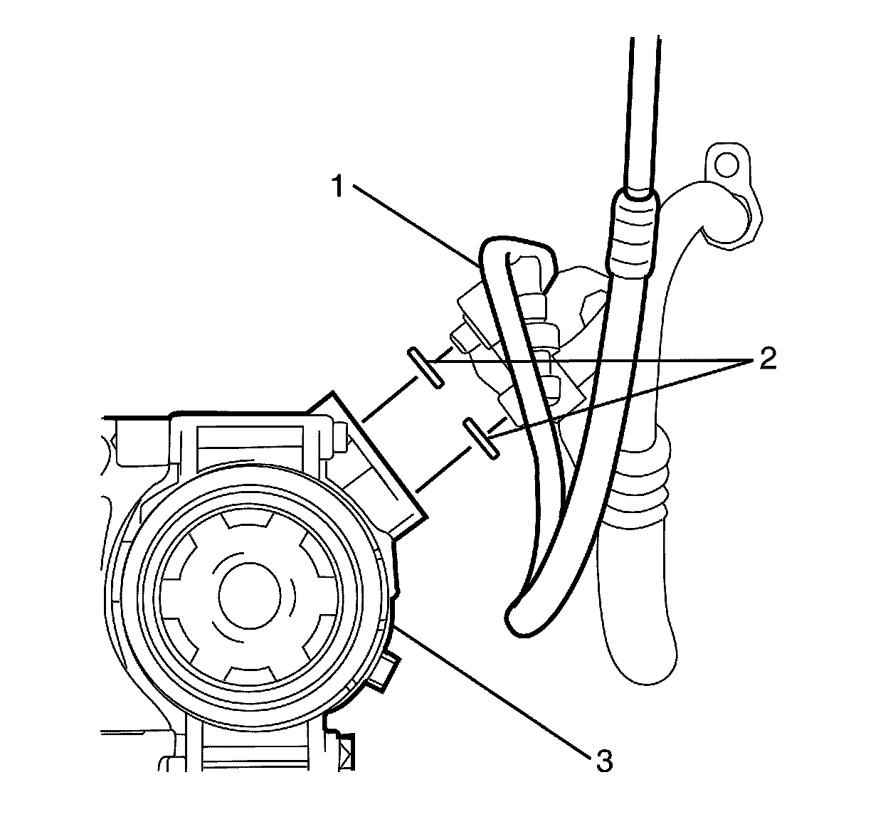
40. Disconnect the A/C suction/discharge line pad (1) from the A/C compressor (3).
Note:
Plug the A/C suction/discharge pipe ends and the compressor ports immediately to prevent contamination and absorption of moisture from the atmosphere.
41. Plug or cap the A/C suction/discharge pipe (1) ends and the compressor (3) ports.
Note:
The A/C sealing O-rings (2) are a single use components. Install NEW A/C sealing O-rings (2) whenever the A/C suction/discharge line pad (1) is removed from the A/C compressor (3).
42. Remove the A/C suction/discharge pipe sealing O-rings (2).
Discard the O-rings (2).
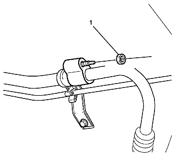
43. Remove the A/C suction pipe pad to A/C suction pipe retaining nut (1).
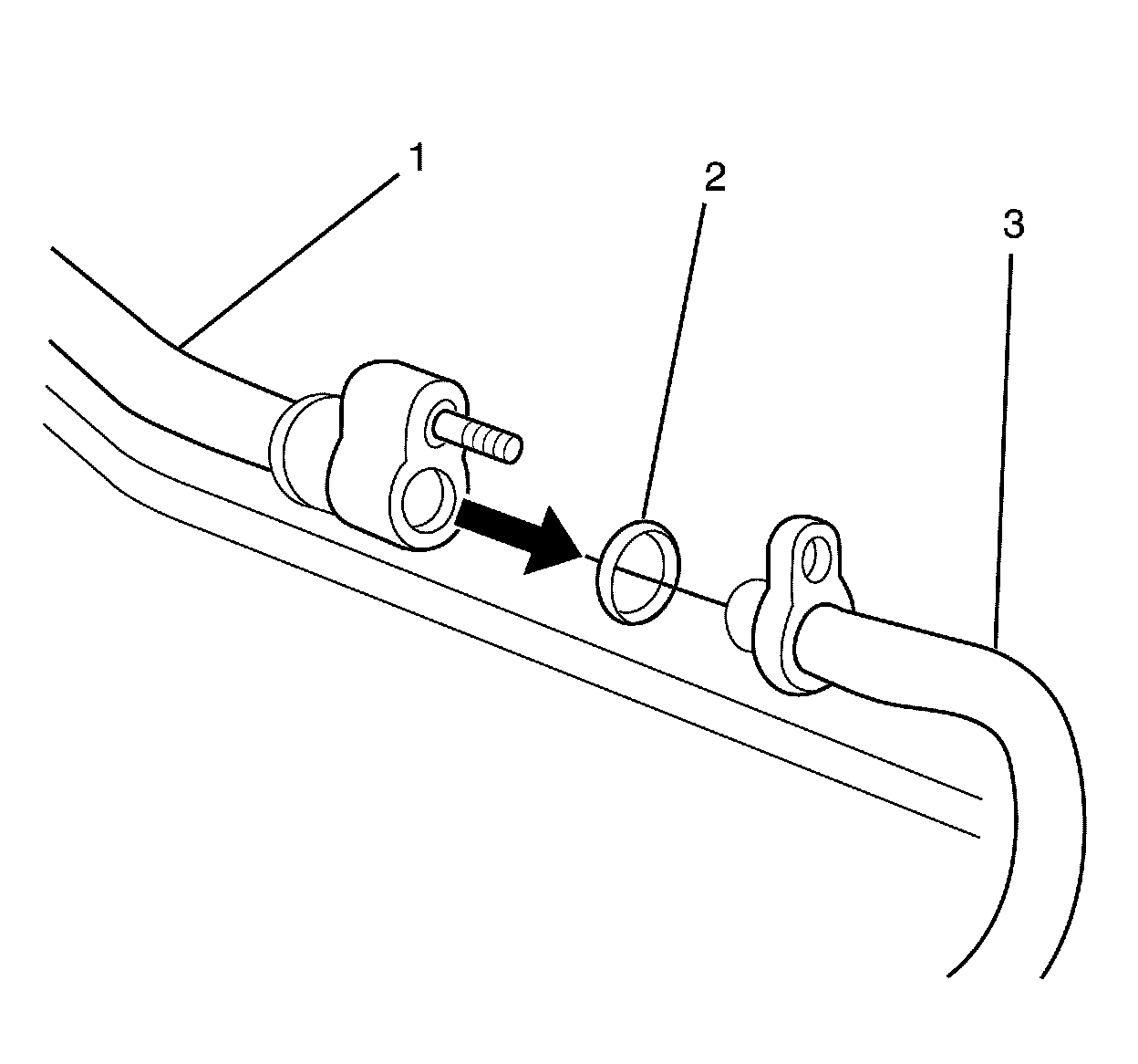
44. Disconnect the upper A/C suction pipe (1) from the lower A/C suction tube (3).
Note:
Plug or cap the A/C suction pipe ends (1 and 3) immediately to prevent contamination and absorption of moisture from the atmosphere.
45. Plug the A/C suction pipe ends.
Note:
The A/C suction pipe sealing O-ring (2) is a single use component. Install a NEW A/C suction pipe sealing O-ring (2) whenever the upper A/C suction pipe (1) is removed from the lower A/C suction pipe (3).
46. Remove the A/C suction pipe sealing O-ring (2).
Discard the O-ring (2).
47. Reposition and secure the A/C suction/discharge pipes away from the engine.
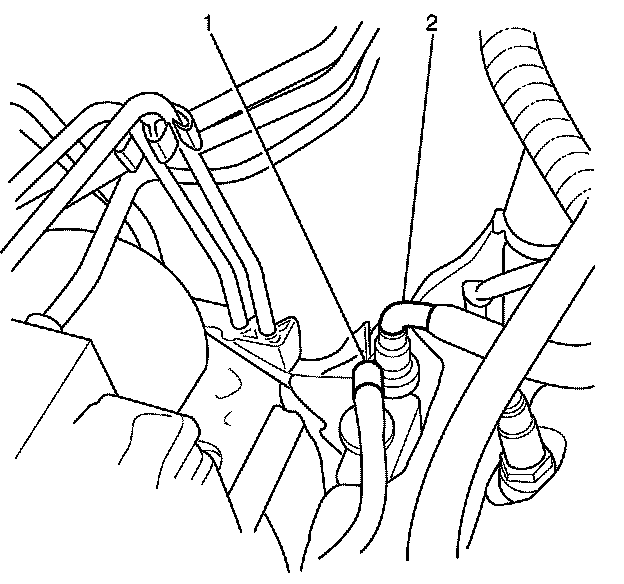
48. Disconnect the fuel feed hose (2) from the fuel feed pipe. Refer to Metal Collar Quick Connect Fitting Service Service and Repair.
Note:
Plugging or capping pipes and hoses prevents leaks or contamination.
49. Plug or cap the ends of the fuel feed pipe (2) and fuel feed hose (1).
50. Disconnect the EVAP emission hose (1) from the EVAP emission pipe. Refer to Plastic Collar Quick Connect Fitting Service Procedures.
Note:
Plugging or capping pipes and hoses prevents leaks or contamination.
51. Plug or cap the ends of the EVAP purge hose and the EVAP purge pipe.
52. Use a suitable container to catch any draining transmission fluid.
Note:
Plugging or capping pipes and hoses prevents leaks or contamination.
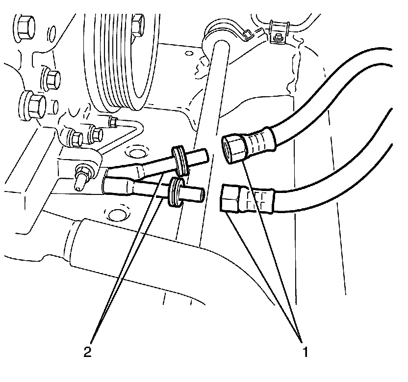
53. Disconnect the flexible hoses (1) from the transmission cooler lines (2) using the cooler quick connect tool J 41623-B. Refer to Metal Collar Quick Connect Fitting Service Service and Repair.
54. Reposition the flexible hoses (1) away from the engine and subframe.
Note:
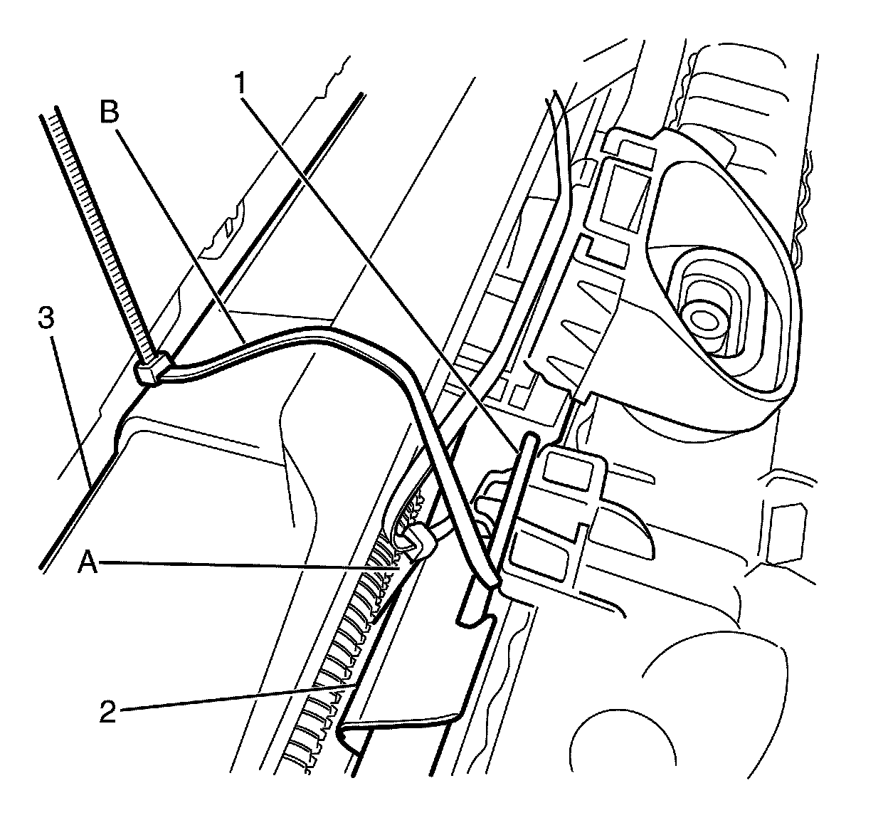
The radiator and condenser assembly is supported by the subframe. To support the radiator and condenser assembly after the subframe is removed, suitably secure the radiator and condenser assembly to the front end assembly.
55. Secure radiator and condenser assembly (2) to the front end assembly (3) with large zip ties (B) or an equivalent.
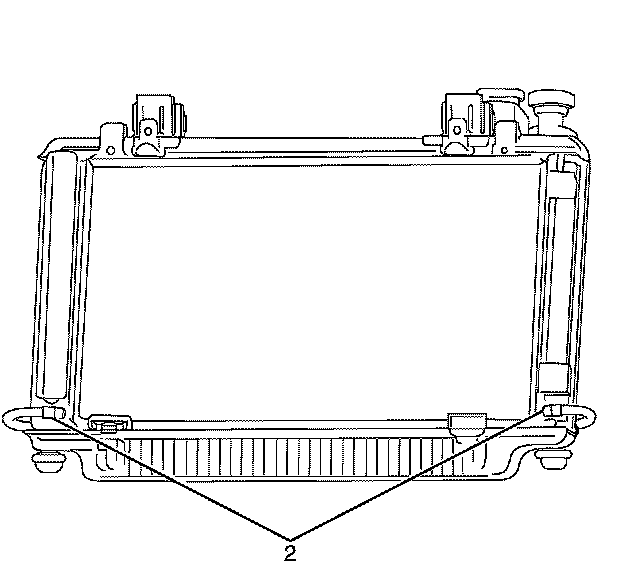
56. Disconnect the power steering cooler hoses (2).
Note:
Plugging or capping pipes and hoses prevents leaks or contamination.
57. Plug or cap the ends of the power steering cooler hoses (2).
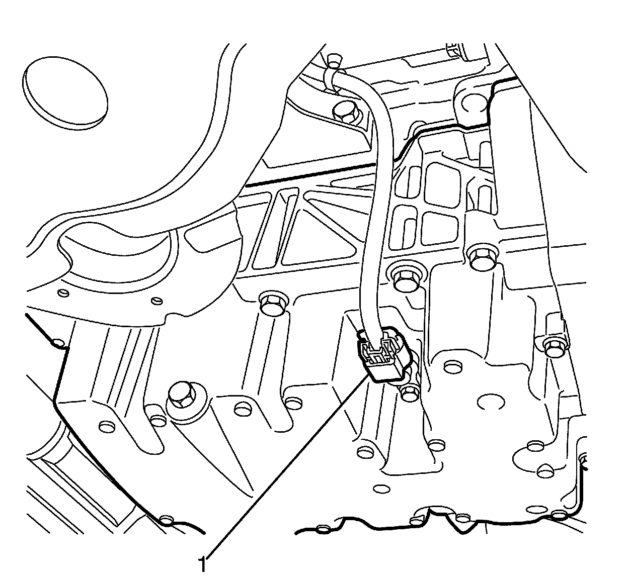
58. Disconnect the oil level/temperature sensor electrical connector (1).
59. Remove the exhaust system for access. Refer to Exhaust System Replacement (V6) Service and RepairExhaust System Replacement (V8) Service and Repair.
60. Remove the centre exhaust heat shield. Refer to Exhaust Heat Shield Replacement - Center Exhaust Heat Shield Replacement - Center.
61. Remove the propeller shaft. Refer to Propeller Shaft Replacement (Except 4L60) Propeller Shaft Replacement (Except 4L60).
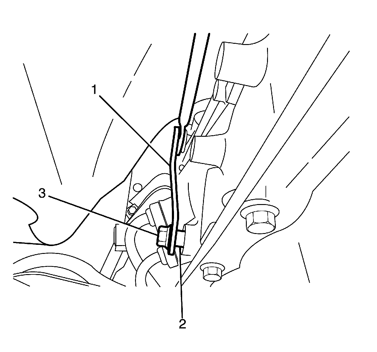
62. Remove the shift selector linkage rod to shift selector shaft retaining nut (3).
63. Remove the shift selector linkage rod (1) from the shift selector shaft (2).
Note:
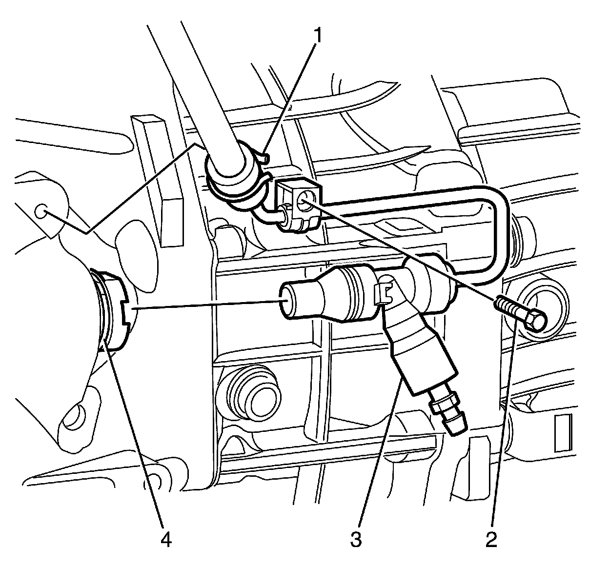
Steps 65 to 72 are for vehicles fitted with a manual transmission.
64. Remove the gearshift lever boot.
65. Detach the flexible hose securing clip (1).
66. Remove the concentric actuator cylinder feed pipe bracket to transmission retaining bolt (2).
67. Release the bleeder assembly securing clip (4), by using a suitable tool and releasing it from the bleeder adapter.
68. Remove the bleeder assembly (3) from the bleeder adapter.
69. Reposition the bleeder assembly (3) away from the transmission with heavy mechanics wire or an equivalent.
70. Remove the starter motor. Refer to Starter Replacement (L77) Service and RepairStarter Replacement (LFX) Service and Repair.
71. Partially lower the vehicle.
72. Remove the front wheels. Refer to Tire and Wheel Removal and Installation Service and Repair.
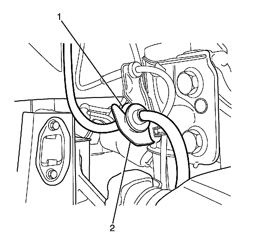
73. Detach the front brake hose (1) from the strut mounted brake hose retaining bracket (2).
74. Repeat for the opposite side.
Note:
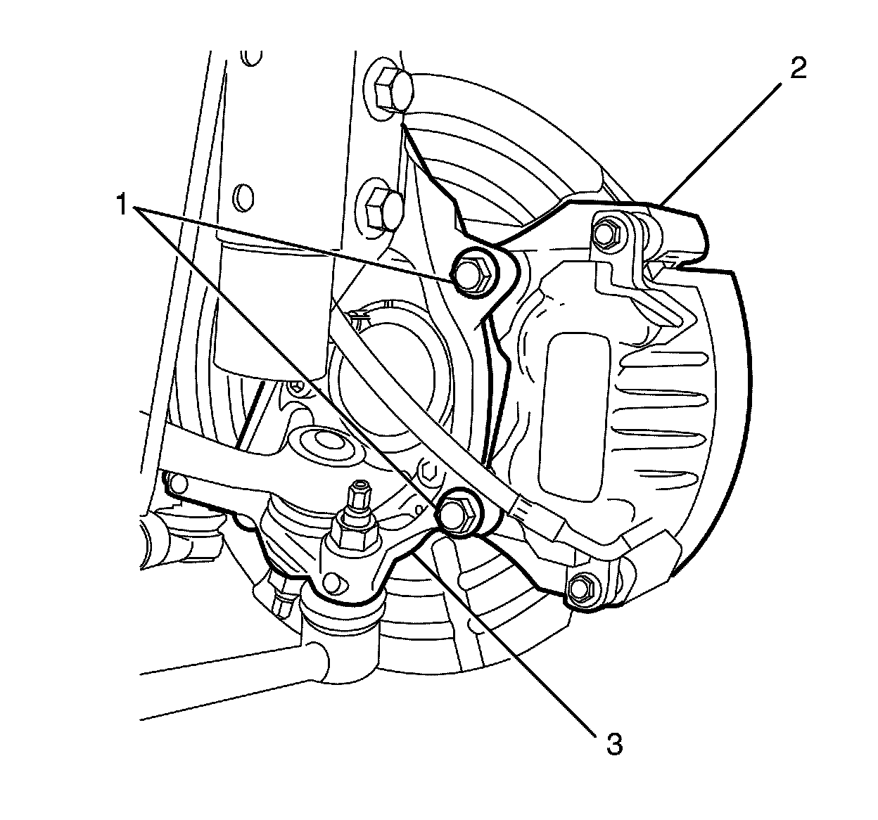
* Bolts with micro-encapsulated thread sealant must be discarded after removal.
* Make sure all the bolt threaded holes are thoroughly cleaned and all micro-encapsulated thread sealant is removed.
75. Remove the front brake caliper anchor plate to knuckle retaining bolts (1).
* Discard the bolts.
* Clean the bolt threaded holes.
Note:
DO NOT disconnect the hydraulic brake flexible hose from the brake caliper. If the hydraulic brake flexible hose is disconnected from the brake caliper complete bleeding of the braking system will be required.
76. Remove the front brake caliper (2) from the front steering knuckle (3).
77. Repeat for the opposite side.
Caution:
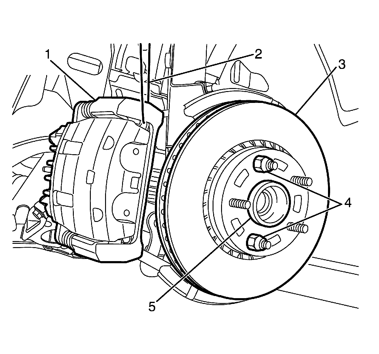
Support the brake caliper with heavy mechanic wire, or equivalent, whenever it is separated from its mount and the hydraulic flexible brake hose is still connected. Failure to support the caliper in this manner will cause the flexible brake hose to bear the weight of the caliper, which may cause damage to the brake hose and in turn may cause a brake fluid leak.
78. Support the front brake caliper (1) with heavy mechanic's wire, or equivalent (2).
79. Install two wheel nuts (4) to retain the front brake disc (3) to the hub (5).
80. Repeat for the opposite side.