Display and Control Unit Overview
Display and Control Unit Overview
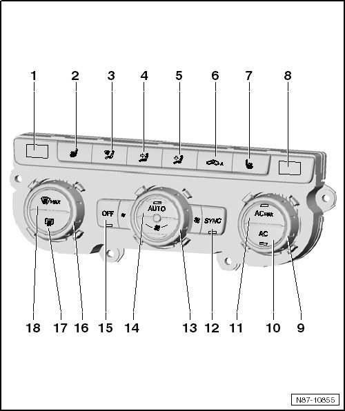
1 Left Temperature Display
• Shows the temperature set for the driver side.
2 Left Seat Heating Button
• The LED is on when the setting is active.
• The seat heating has 3 settings. An LED indicates which setting is selected.
3 Windshield Air Distribution Button
• The LED is on when the setting is active.
4 Center Air Distribution Button
• Air distribution to the upper body via the center vents
• The LED is on when the setting is active.
5 Lower Air Distribution Button
• Air distribution in the footwell.
• The LED is on when the setting is active.
6 Air Recirculation Button
• The LED is on when the setting is active.
• Manual and automatic recirculating air mode.
• Press the button for recirculating air function to prevent polluted air from entering interior.
Recirculating air is switched on automatically under the following conditions:
• When the windshield washer system is operated,
• When the Air quality sensor (G238) is activated,
• When the reverse gear is engaged (this function is only active for 2 minutes after the engine is started).
• Blower speeds on Front A/C display control head (E87) ,
• Front A/C display control head (E87) "OFF".
7 Right Seat Heating Button
• The LED is on when the setting is active.
• The seat heating as 3 settings. An LED indicates which setting is selected.
8 Right Temperature Display
• Shows the temperature set for the front passenger side.
9 Right Temperature Control
• The selected temperature will be shown in the display.
10 AC Button
• The LED is on when the setting is active.
• If the AC button is deactivated, the A/C compressor is set to almost zero delivery. If the AUTO button is activated, the heating and ventilation mode continues to be controlled electronically.
11 MAX AC Button
• The LED is on when the setting is active.
• Run A/C system with MAX A/C.
12 Sync Button
• The LED is on when the setting is active.
• Current driver side temperature control supersedes that of the front passenger side.
13 Blower Control
• By turning the knob, the blower speed can be individually adjusted.
• If the blower speed is manually adjusted, the function AUTO is automatically deactivated.
14 AUTO Button
• The LED is on when the setting is active.
• In automatic mode the Climatronic maintains the selected vehicle temperature automatically. The air temperature, the blower speed and the air distribution are adjusted automatically.
15 OFF Button
• Press the OFF button to turn off the heater and A/C.
16 Left Temperature Control
• The selected temperature will be shown in the display.
17 Rear Window Defogger Button
• The LED is on when the setting is active.
• It only works when the engine is running and turns off on its own after 10 minutes.
18 Max Defrost Button
• Air sucked in from the outside is directed to the windshield causing the recirculating air mode to shut off automatically.
• In order to remove fog from front windshield as quick as possible, the air must be warmed to a temperature over 1.5 °C (+ 35 °F) and the blower must reach a high blower speed.
Display and Control Unit Connectors
Special tools, testers and auxiliary items required
• Test Adapter (V.A.G1598/47)
• Due to differences in equipment levels, use the most current wiring diagram to find the exact assignment of the individual connector positions and pin assignments.
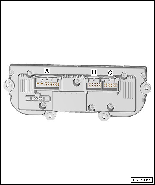
A - Connector 20-pin
• Due to differences in equipment levels, use the most current wiring diagram to locate the connector and pin assignments.
B - Connector 16-pin
• Due to differences in equipment levels, use the most current wiring diagram to locate the connector and pin assignments.
C - Connector 16-pin
• Due to differences in equipment levels, use the most current wiring diagram to locate the connector and pin assignments.